4 Ways to Wire GFCI

Introduction
Ground fault circuit interrupters (GFCI) are essential safety devices in modern electrical systems. They help to protect users from electrical shocks by detecting ground faults and promptly breaking the circuit. In this article, we will discuss four ways to wire GFCI in your home or office.
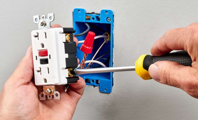
1. Wiring a GFCI Receptacle
A GFCI receptacle is a common type of GFCI device that replaces a standard electrical outlet. Here’s how to wire it:
a. Turn off the power supply and verify using a voltage tester.
b. Remove the existing outlet from the wall.
c. Identify the line wires (hot and neutral) coming from the main electrical panel.
d. Connect the black (hot) line wire to the brass terminal marked “line” on the GFCI receptacle.
e. Connect the white (neutral) line wire, from the main panel, to the silver terminal marked “line” on the GFCI receptacle.
f. Attach both ground wires to the green terminal on the receptacle.
g. Carefully push back and secure the outlet into place.
h. Restore power and test using a GFCI tester.
2. Wiring a GFCI Breaker
A GFCI circuit breaker protects an entire circuit from ground fault hazards at your main electrical panel:
a. Turn off power supply to your entire house and open your breaker box.
b. Remove an existing non-GCFI breaker that you want to replace, by pulling it out from its slot carefully.
c. Insert your new GFCI breaker into an empty slot in your electrical panel.
d. Connect the black (hot) wire from the protected circuit to the brass terminal on the breaker.
e. Connect the white (neutral) pigtail wire provided with your breaker to the neutral bus bar inside the panel.
f. Connect the remaining white (neutral) wire from the protected circuit to the silver terminal on the breaker.
g. Reinstate power and test the operation of the GFCI breaker.
3. Wiring GFCI Outlets in Series
GFCI outlets wired in series allow one GFCI receptacle to provide protection for multiple downstream receptacles:
a. Follow steps a-f as outlined in wiring a GFCI receptacle.
b. Identify load wires (hot and neutral) going to downstream outlets that require GFCI protection.
c. Connect the black (hot) load wire to the brass terminal marked “load” on the GFCI receptacle.
d. Connect the white (neutral) load wire to the silver terminal marked “load” on the GFCI receptacle.
e. Re-secure and test each outlet individually with a GFCI tester.
4. Wiring a GFCI Switch Combo
A GFCI switch combo replaces one switched outlet with a combined GFCI receptacle/switch unit while protecting other downstream outlets:
a. Turn off power supply to the switch, remove it, and identify line, load, and switch wires.
b. Connect all ground wires to the green terminal on the combo unit.
c. Connect both line-side hot and neutral wires to brass and silver terminals marked “line.”
d. Connect load-side hot and neutral wires to brass and silver terminals marked “load.”
e. Attach remaining switch leg wire to brass terminal marked “switch”.
Conclusion
Wiring a GFCI ensures that your electrical system is safe from potential hazards caused by ground faults. Understanding how to properly wire them is crucial for any homeowner or professional electrician alike.


